Project Data
Sets properties for the project. The settings apply only to elements that have not been drawn yet. The parameters of already inserted elements could be modified in the Manifold or Floor Properties.

Project Info
The window defines the data for the whole project.
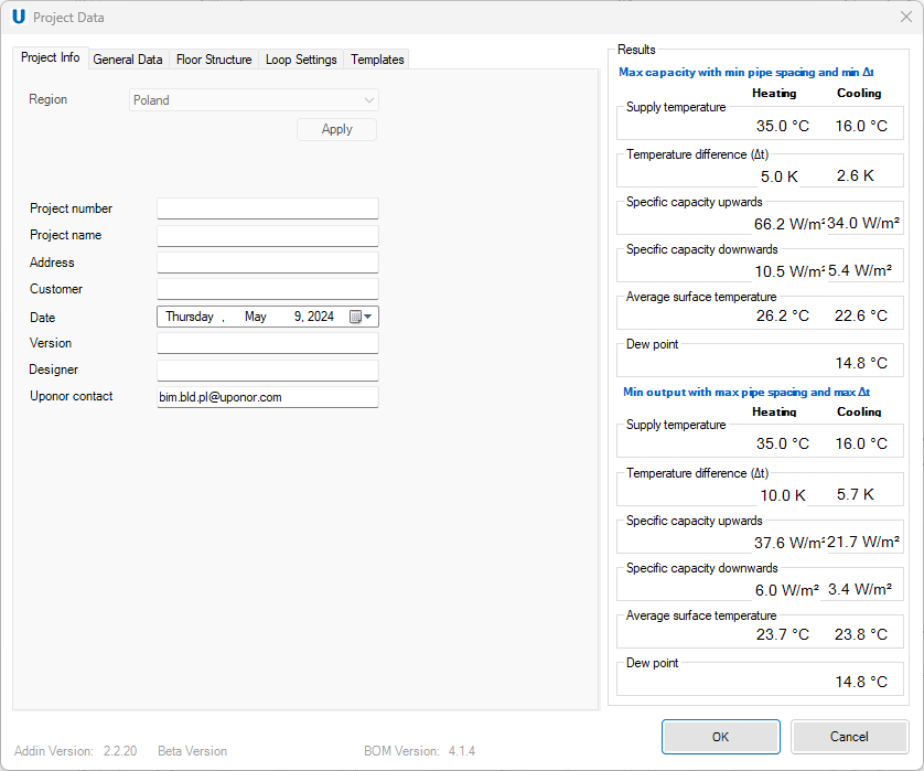
- Region – indicates the products’ portfolio range available for the selected region. The bill of materials includes only the products that are saleable in the selected country's portfolio.
Note! This setting cannot be changed later!
-
Project number – project number assigned by the user.
-
Project name – contains the most important phrases for easy identification.
-
Address – investment address.
-
Customer – name and surname of the customer.
-
Date – date of project creation.
-
Version – current version of the project.
-
Designer – name and surname of the customer.
-
Uponor contact – e-mail contact person at Uponor.
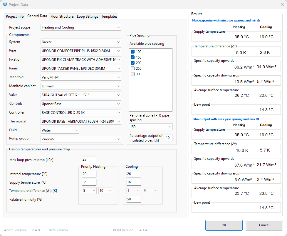
General Data
The window defines the project scope. The settings apply only to elements that have not been drawn yet. The parameters of already inserted elements could be modified in the Manifold or Floor Properties.
-
Project scope – choosing the scope of the project between heating, cooling or a mix of both. In the case of a combined choice, it's essential to determine the priority mode (the first mentioned).
-
Components – necessary elements to create a complete heating and/or cooling installation. Not all components are mandatory to use: system, pipe, manifold and fluid are crucial to choose.
- System – type of heating/ cooling system available in chosen region.
- Pipe - type of pipe. In the current version, it does not matter what coil length the user chooses. The bill of materials will present the total length of pipe.
- Panel – type of pipe holder panel or an additional insulation.
- Manifold – type of the hub of a heating/cooling system, connecting both the supply and return lines in a central place. It allows the distribution of heated/cooled water from the source to different circuits of the underfloor heating/cooling system.
- Manifold cabinet – specialized enclosure designed to house the manifold components.
- Valve – control the flow of the fluid within the system.
- Controls – type of control system.
- Controller – temperature measuring instrument and controls module.
- Thermostat – monitors the room temperature and sends signals to adjust the heat outputs.
- Fluid – fluid in underfloor heating/cooling system distributes heat/cold to area around the floor.
- Pump group – consolidated unit comprising essential components vital for fluid circulation and regulation within heating/cooling systems. Its main function is to limit the temperature of the fluid entering the manifold.
Note! Only pipes and manifolds will be used as Revit families in the model.
The rest of components will only be added to the bill of materials.
-
Design temperatures and pressure drop – the temperatures and pressure data used for calculations.
- Max loop pressure drop [kPa] – maximum pressure value. If exceeded, the software will display an error.
- Internal temperature [°C] – indoor room temperature.
- Supply temperature [°C] – fluid temperature leaving the manifold.
- Temperature difference Δt [K] – temperature difference of the supply and return fluid.
- Relative humidity [%] – indicates the current state of absolute humidity relative to the maximum humidity possible at the same temperature.
-
Pipe spacing – distance between the pipes in the loop.
- Available pipe spacing – pipe spacing to be used in the project. Plugin will choose one of the selected pipes spacing to achieved optimal heating output.
- Peripheral zone pipe spacing – distance between pipes in a loop in a part of the room where greater output is necessary.
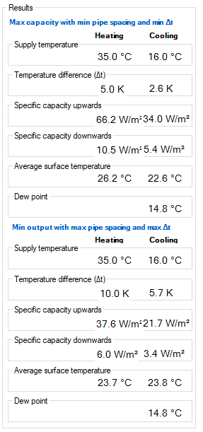
Results
Part of the Project data window with preview of the results. By changing some parameters user can influence the results. The pipe spacing and the temperature difference between the supply and return can significantly change the specific capacity values. Moreover, in the Floor Structure tab, modifications to the floor covering types can also influence the obtained results.
-
Max capacity with min pipe spacing and min Δt – the maximum outputs displayed based on chosen parameters.
-
Min output with max pipe spacing and max Δt – the minimum outputs displayed based on chosen parameters.
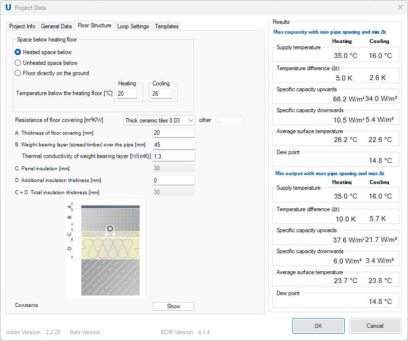
Floor Structure
The window defines floor layers. The settings apply only to elements that have not been drawn yet. The parameters of already inserted elements could be modified in the Manifold or Floor Properties.
-
Space below heating floor – determining the space under the heated/cooled floor.
- Heated space below – there is a heated space under the heated/cooled floor.
- Unheated space below – there is an unheated space under the heated/cooled floor.
- Floor directly on the ground – there is a ground under the heated/cooled floor.
- Temperature below the heating floor [°C] – determines the temperature in the space below the heated/cooled floor for heating and cooling.
-
Resistance of floor covering [m²K/W] – determines the type of floor covering and its resistance.
- A. Thickness of floor covering [mm]– thickness of the first top layer of flooring.
- B. Weight bearing layer (screed/timber) over the pipe [mm] – layer with structure that bear the weight or load providing structural support over the pipe.
Thermal conductivity of weight bearing layer [W/(mK)] – measure of ability to transfer the heat through the weight bearing layer. - C. Panel insulation [mm] – thickness of panel under pipes (value automatically taken from the General Data tab).
- D. Additional insulation thickness [mm] – thickness of an insulation in addition to the panel.
- C+D. Total insulation thickness [mm] – the sum of panel insulation and additional insulation.
-
Constants – values considered as constants for program calculations.

- Thermal conductivity of the insulation [W/(mK)] – measure of ability to transfer the heat through the insulation.
- Structural base layer thickness [mm] – thickness of main structural layer on the floor.
- Thermal conductivity of the structural base [W/(mK)] – measure of ability to transfer the heat through structural base.
Loop settings
The window defines loop laying shape. The settings apply only to elements that have not been drawn yet. The parameters of already inserted elements could be modified in the Floor Properties.
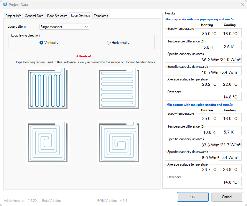
- Loop pattern – there are two types of loop pattern.
- Single meander
- Spiral
- Loop laying direction – there are two types of loop direction.
- Vertically
- Horizontally
Templates
The window with Multiple templates with different project data settings (e.g. different systems) can be created to speed up the preparation of future projects.
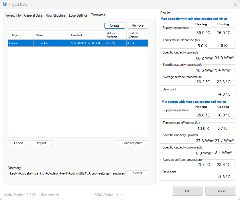
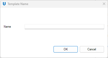
- Create – after clicking create button new window will appear. Here user should provide a unique name of a new template.
- Remove – after clicking remove button the selected template will be vanished.
-
Export – after clicking export button the user could save the file on local disk.
-
Import – after clicking import button the user could choose the template file (.group extension) from local disk and save it on the template list in the plugin.
- Load template – after clicking load template button the chosen template will be provided into all general data tabs.