Hydraulic Calculations
Hydraulic Calculations information needed to check the project.

After entering all information, inserting the components into the drawing and assigning floors to manifold the user can perform the hydraulic calculations.
Calculation has to be generated when loops and feed pipes are not created on the drawing, thanks to which the plugin will adjust the appropriate spacing of connectors in the floors. In this case program takes virtual loop and feed pipes to calculation. This option is used to create initial calculations. Second option is to create hydraulic calculation with virtual loops and real feed pipes. And in the third and most accurate option, the user generates hydraulic calculations based on real loops and real feed pipes.
To generate calculations the user should click on the Hydraulic Calculation button on the ribbon. In Hydraulic Calculations window, the user can determine and control if created heating floors have the appropriate calculation results and if necessary, make suitable changes.
After clicking Hydraulic Calculations function on the ribbon, the Select manifold window will appear. There is a possibility to calculate results for selected manifolds - separately or for all existing manifolds on the drawing . Using the check all or check none buttons, the user can quickly make a selection.
Visibility of manifolds on the list
-
All objects in current project – if checked, all manifolds existing in the model will appear on the list.
-
Only selected objects – if checked, all selected manifolds in the model will appear on the list.
-
Filter by – helps to filter manifolds by levels.
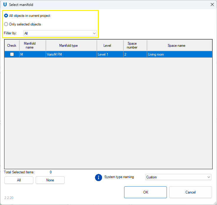
System type naming
Form this drop-down list the user could choose system type naming.
- Custom – user can name system type arbitrarily.
- Default – all pipes of the underfloor heating/cooling system will automatically have the following system assigned: UPO_Supply, UPO_Return, UPO_Loop. If the user selects Default, please be aware that the software will overwrite any previous changes you made to System types.
Warnings window
After selecting manifolds and click OK the Warnings window might be displayed. Here is presented the list of errors which occur in the hydraulic calculations or when data is not completed. The user can close the window and proceed to make corrections. It is up to the user which of the warnings he considers necessary to improve and which he ignores.
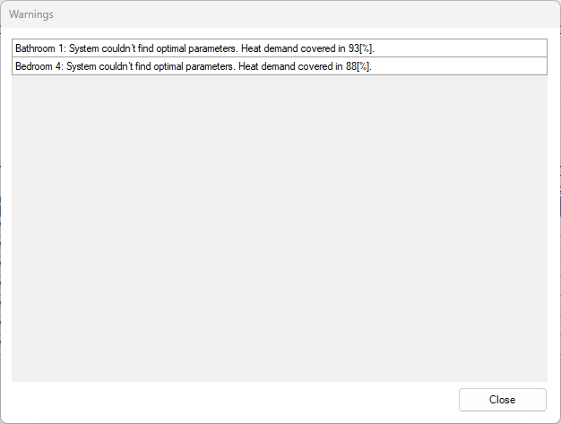
If the user would like to preview the warnings again, they will be displayed after clicking the Warnings button on the right.
To locate warnings in Manifolds and Floors tables, the program highlights cells with errors in red.
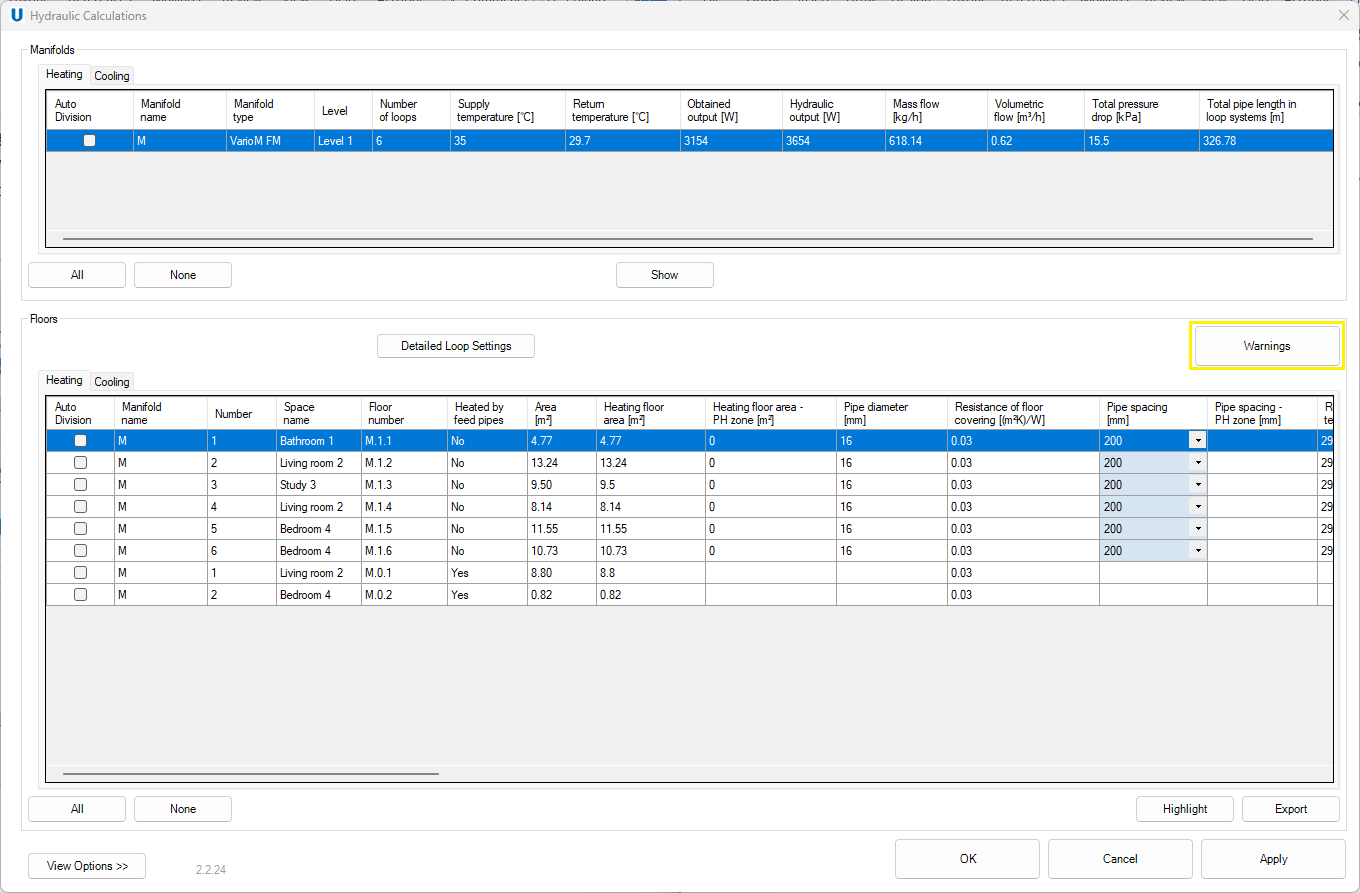
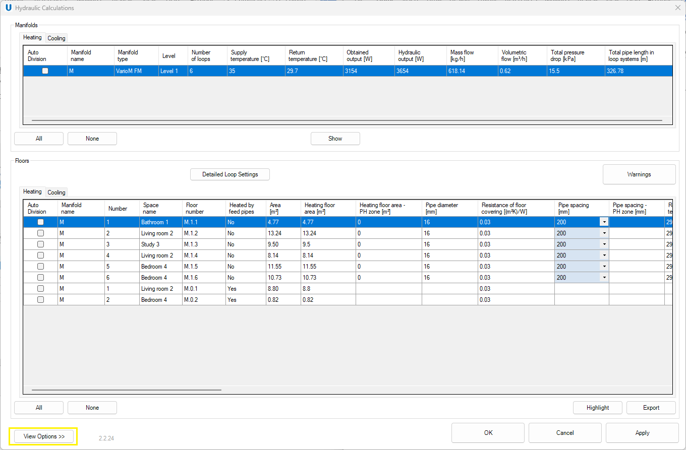
Tables with results
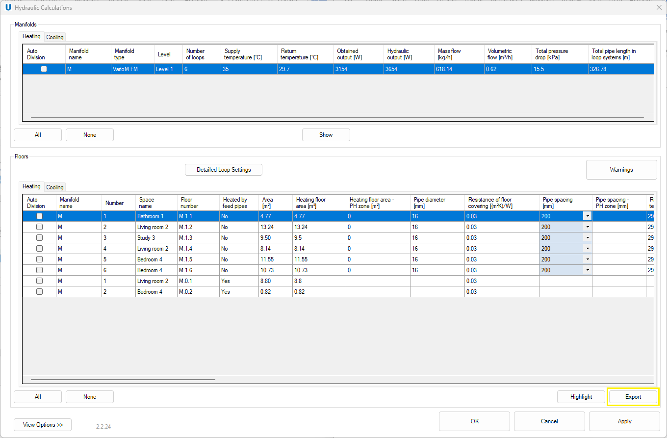
The Hydraulic Calculations window consist of two parts: Manifolds and Floors.
Manifold
The Manifolds table enables to preview the main heating and cooling results for each manifold in the project. Click to the manifold causes linked floor to be displayed in the floor’s properties window below. By holding Ctrl key the user can select larger amount of manifolds. Depending on the selected tab, results for heating and cooling are displayed.
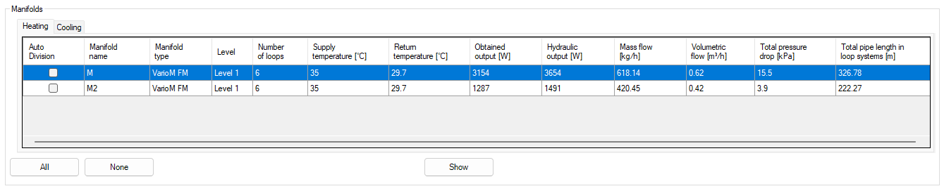
- Manifold name – unique name of manifold.
- Manifold type – Uponor type of the manifold.
- Level – location of the manifold.
- Number of loops – number of connected loops.
- Supply temperature [°C] – fluid temperature leaving the manifold.
- Return temperature [°C] – fluid temperature returning to the manifold.
- Obtained output [W] – total obtained output from all loops connected to the manifold.
- Hydraulic output [W] – total obtained output extended of heating/cooling looses from all loops connected to the manifold.
- Mass flow [kg/h] – total mass flow rate of heating/cooling fluid through the manifold.
- Volumetric flow [m³/h] – total flow of heating/cooling fluid through the manifold.
- Total pressure drop [kPa] – total pressure drop from connected loops and manifold.
- Total length in loop system [m] – total loops and feed pipes length.
Show button
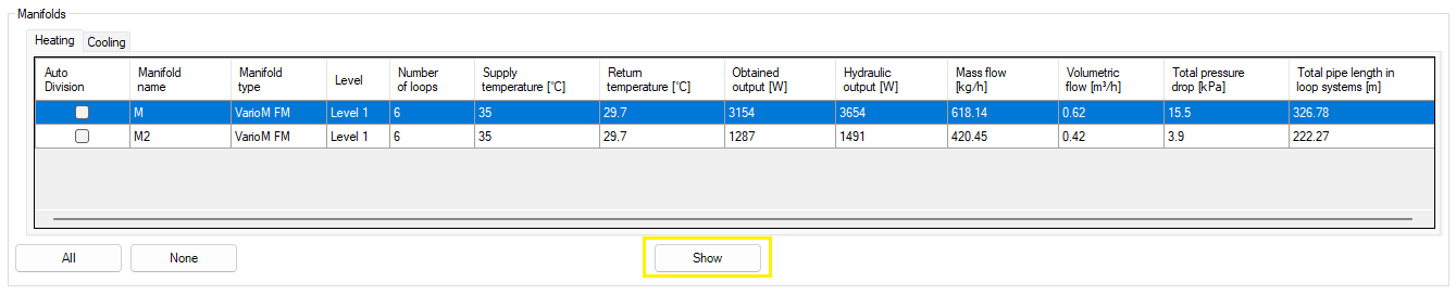
After selecting one row with manifold in the manifold table and clicking Show button, program will present the location of the selected element in the open view and the Show Elements window will appear.
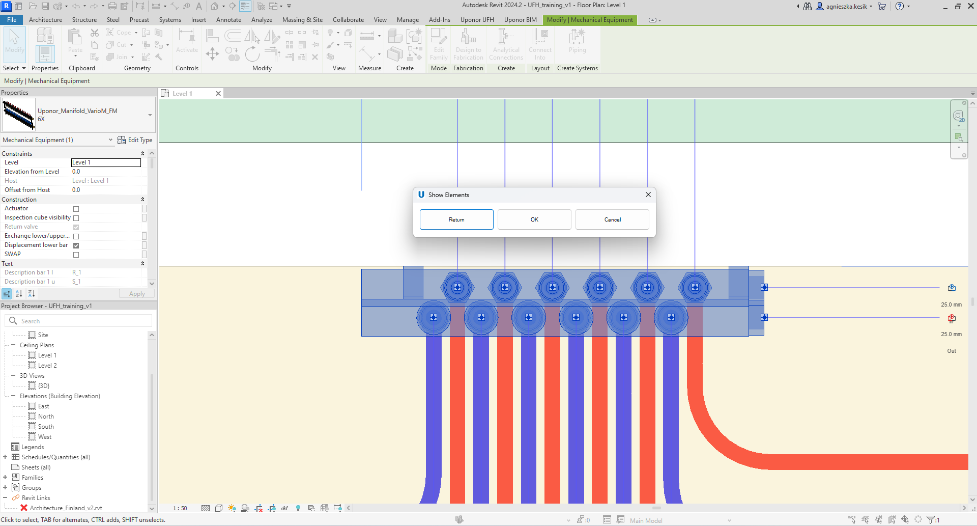
- Return – the user will return to Hydraulic Calculations window.
- OK – the user accepts changes in Hydraulic Calculations window and close it.
- Cancel – the user DO NOT accept changes in Hydraulic Calculations window and close it.
Floors
The Floors table enables to preview the main heating and cooling results for each floor connected with indicated manifolds. Depending on the selected tab, results for heating and cooling are displayed.
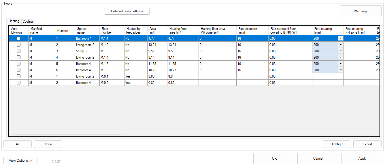
- Auto Division – once selected, the program will divide the floor into the indicated number of parts from column Number of suggested parts when the user accepts the changes by clicking Apply or OK button.
- Manifold name – unique name of manifold.
- Number – the number of the loop connected to the manifold.
- Space name – the name of space in which the floor is located.
- Floor number – floor number containing information about the connected manifold and loop number.
- Heated by feed pipes –information about floor type . Yes - floor heated by feed pipes. No - standard floor with loop.
- Area [m²] – total area of heated /cooled floor (main and peripheral zone). Heating floor area [m²] – area of heated floor (main zone).
- Heating floor area – PH zone [m²] – area of heated floor (peripheral zone).
- Pipe diameter [mm] – outer diameter of the pipe.
- Resistance of floor covering [(m²K)/W] – ensures heat transfer efficiency. The value depends on the floor surface material.
-
Pipe spacing [mm] – distance between pipes in the loop in the main zone.
Note! There is a possibility to provide a new value by clicking on the appropriate cell and selecting different value from the dropdown list. After accepting the change by clicking Apply button, new calculated values will appear in the tables. -
Pipe spacing – PH zone [mm] – distance between pipes in the loop in the peripheral zone.
- Return temperature [°C] – calculated temperature of return fluid.
-
Δt [K] – temperature drop of the heating fluid (between supply and return temperature).
Note! There is a possibility to provide a new value by clicking on the appropriate cell and selecting different value from the dropdown list. After accepting the change by clicking Apply button, new calculated values will appear in the tables. -
Surface temperature [°C] – calculated temperature of floor surface in main zone.
- Surface temperature – PH zone [°C] – calculated temperature of floor surface in peripheral zone.
- Specific capacity [W/m²] – calculated heating/cooling capacity per area in main zone.
- Specific capacity – PH zone [W/m²] – calculated heating/cooling capacity per area in peripheral zone.
- Design heating load [W] – required heating/cooling output for loop.
- Obtained output [W] – the amount of heat/cool received from the loop.
- Heating coverage [%] – percentage coverage of heat/cool demand.
- Area covered by passing feed pipes [m²] – calculated area of floor heated/cooled by uninsulated feed pipes in transit.
- Obtained output from passing feed pipes [W] – the amount of heat/cool received from passing feed pipes.
- Loop length in floor [m] – total length of pipes in the loop within floor area.
- Feed pipes length [m] – total length of pipes connecting the loop to the manifold.
- Total loop length [m] – the sum of loop length in floor and feed pipes length.
- Mass flow [kg/h] – total mass flow rate of heating/cooling fluid through the loop.
- Flow velocity [m/s] – total velocity of heating/cooling fluid through the loop.
- Reynolds number – value to determine whether the flow is laminar or turbulent.
- Loop pressure drop [kPa] – value of pressure drops for the loop.
- Valve pressure drop [kPa] – value of pressure drops for the valve in manifold.
- Total pressure drop [kPa] – the sum of Loop pressure drop and Valve pressure drop.
- Volumetric flow [l/min] – total flow of heating/cooling fluid through the on each loop - value to set on flowmeters.
- Setting value – Number of Lockshield turns on the Manifold for each loop
- Total loop length + feed pipes (after division) [m] – assumed total length of pipes of the heating/cooling system, including the length of feed pipes for heating/cooling floor after suggested division.
- Total pressure drop (after division) [kPa] – assumed total value of pressure drop for the loop extended of manifold after suggested division.
- Number of suggested parts – suggested number of division parts to avoid exceeding total loop pressure drop. To change this value go to Detail loop settings.
- Division type – floor will be automatically divided horizontally or vertically. To change this value go to Detail loop settings .
Highlight button
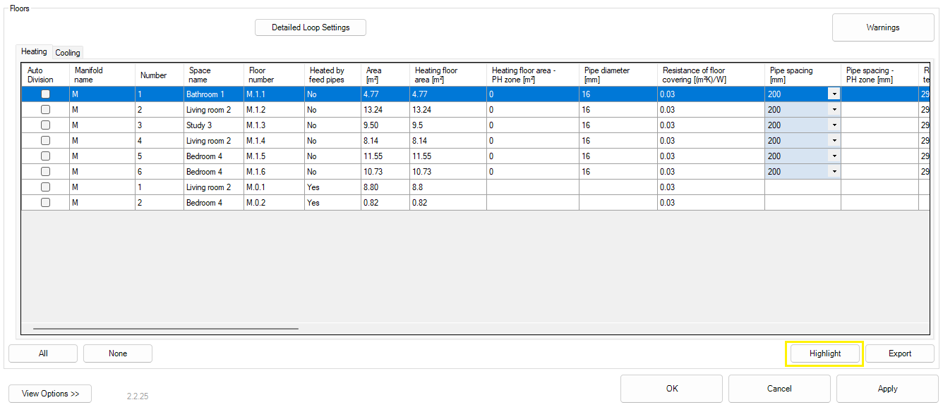
After selecting one row with floor in the Floor table and clicking Highlight button, program will present the location of the selected element in the open view and the Show Elements window will appear.
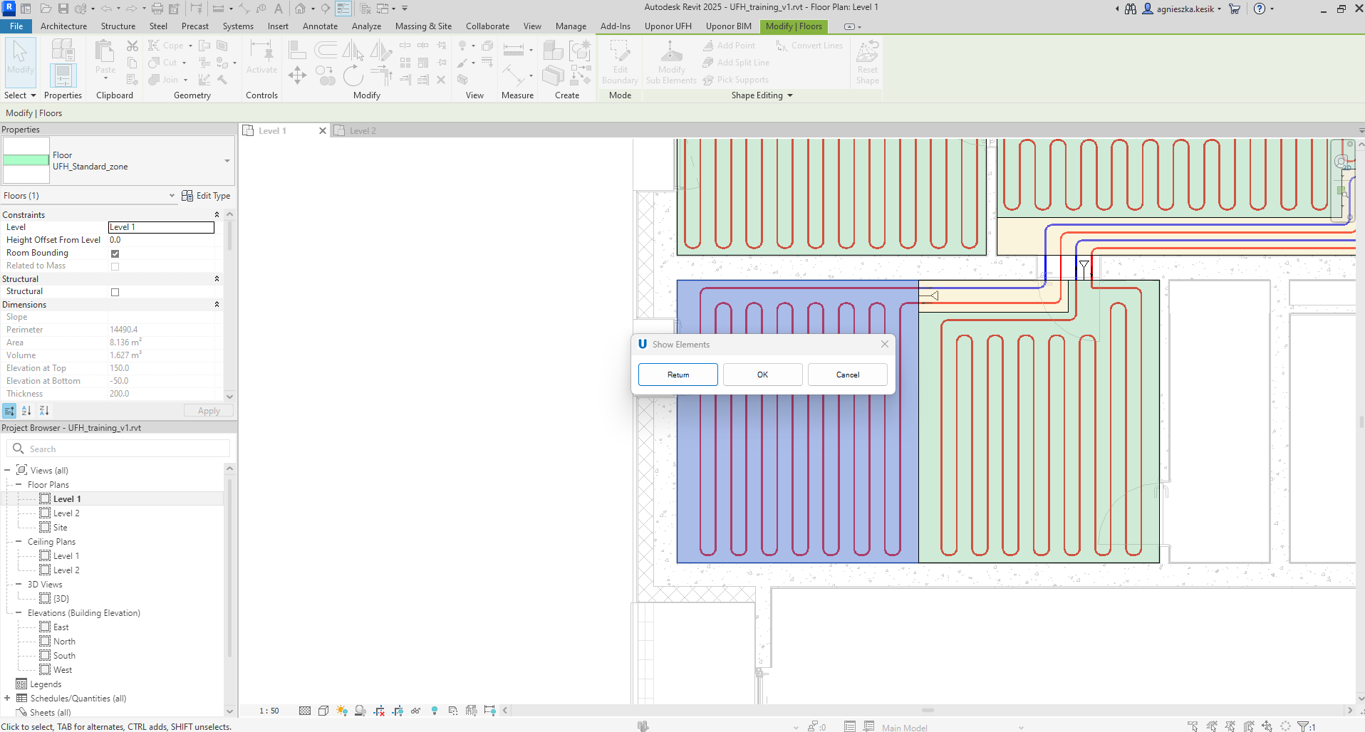
-
Return – the user will return to Hydraulic Calculations window.
-
OK – the user accepts changes in Hydraulic Calculations window and close it.
-
Cancel – the user DO NOT accept changes in Hydraulic Calculations window and close it.
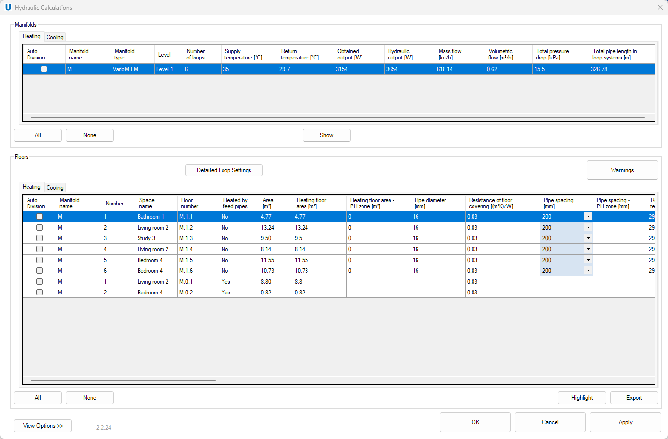
View Options button
Both the Manifolds table and the Floors table have many columns with various data. To adjust the visibility of columns only to those necessary, click the View Options button and select or unselect the columns.
The first part is for the Manifold table and the second part is for Floors table. The Plugin remembers the users preferences and in subsequent projects will display the columns selected here by a default.
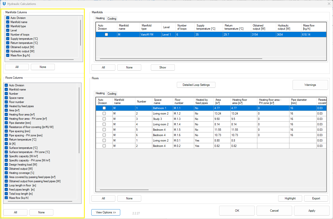
Click the View Options button again to close the list of columns visibility on the left.
Detailed Loop Settings
Export
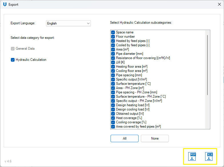
There is also a possibility to export Hydraulic Calculations results by clicking Export button at the bottom of the Hydraulic Calculations window.
An Export window appears in which the user could adjust the printouts to his preferences.
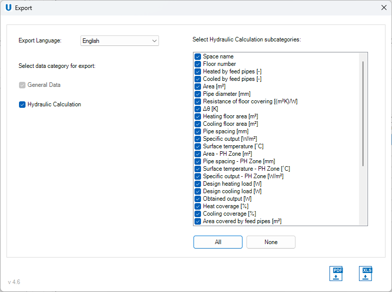
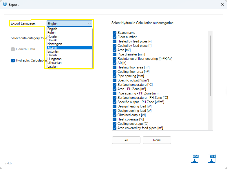
- Export Language – drop-down list with all available languages for the printout.
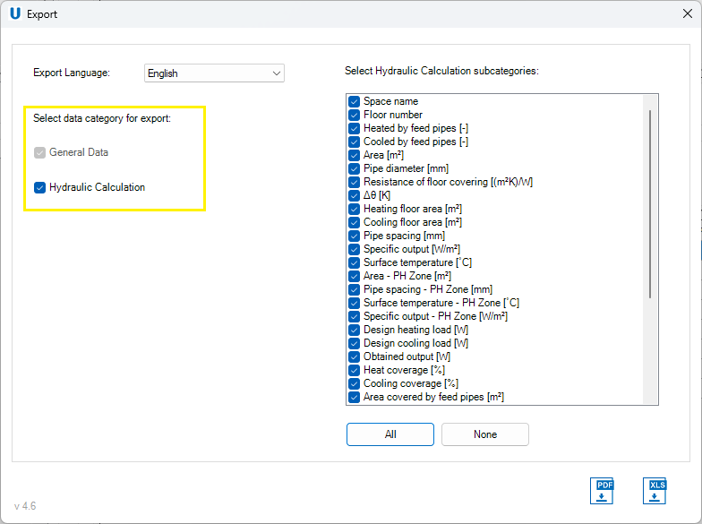
- Select data category for export – selection of categories visible on the printout.
- Select Hydraulic Calculation subcategories – selection of columns with results from Hydraulic Calculation visible on the printout.
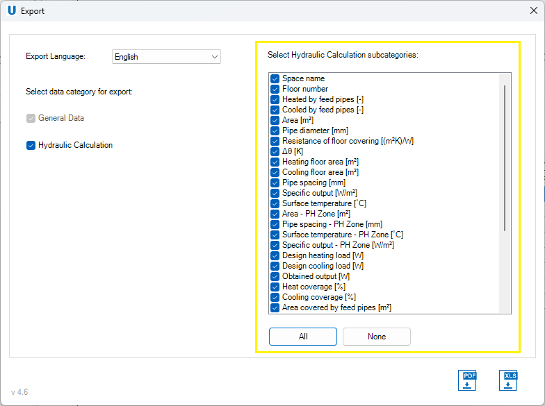
- Export format – the user has two options for exporting the Results: to PDF or to XLS files.
If the user would like to export all results as General data, List of rooms, Hydraulic Calculations and Bill of Materials, he should open Results window and there click Export. More detailed steps are described in the Results section.