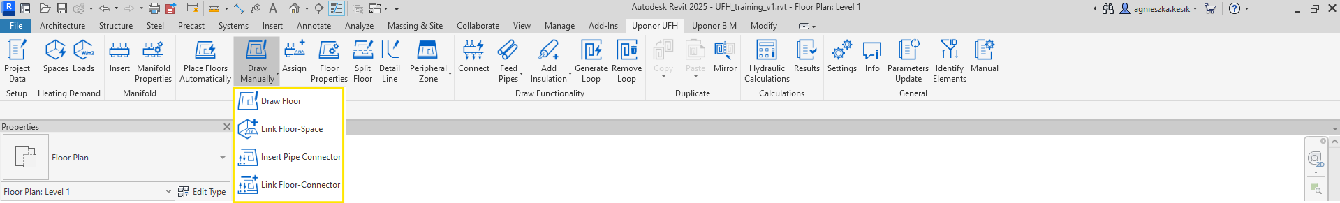
Draw Manually
Manually drawing the floor and assigning it to space.

After clicking the Draw Manually icon, a list of functions will expand.
Draw Floor
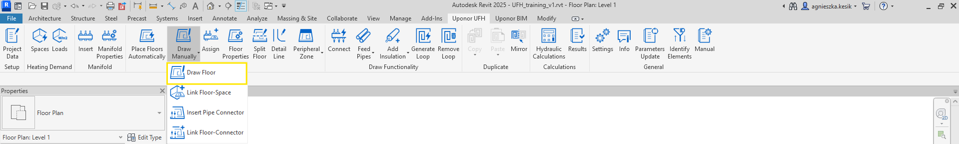
After clicking the Draw Floor icon, the Create Floor Boundary mode on the ribbon is activated.
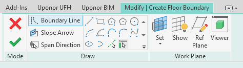
Now user could create the shape of the floor by drawing boundary lines using functions from modify mode. To complete the creation of the floor shape, the user should accept the changes using the green check or reject them by selecting the red cross.
Note! The floor created in this way requires assigning it to space via Link Floor – Space function.
Link Floor – Space
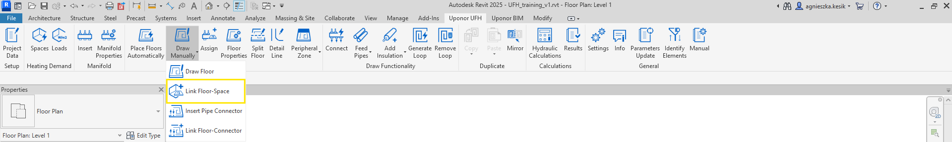
To assign manually created floor to space corresponding space, select both elements and use Link Floor – Space function. Thanks to this, the floor will get important parameters collected in space. When the user correctly links floor and space, the following message will appear.
Pipe Connector
- Pipe Connector –element responsible for connecting the loops in the floor with the feed pipes from the manifold. It consists of four connectors to which the pipes should be connected, arrows informing the user about supply and return, and a triangle which should always be located outside the connected floor.
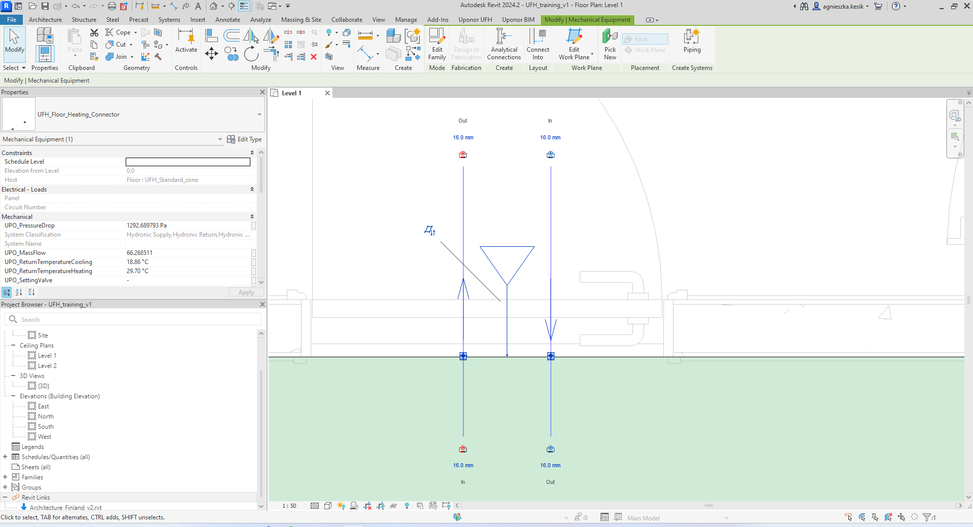
- To change the position of the supply and return, the user should select the Pipe Connector and click the spacebar on the keyboard. The direction of the arrows next to the connector will then change.
- To change the position of Pipe Connector from the inside to the outside of the connected floor, the user should select the Pipe Connector and click Flip Work Plane. The position of rectangle with arrow will change.
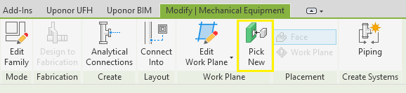
- To change the position of Pipe Connector to another place, the user should select Pipe Connector and move it on the same plane or use function Pick New on the Modify Mechanical Equipment mode on the ribbon.
Insert Pipe Connector
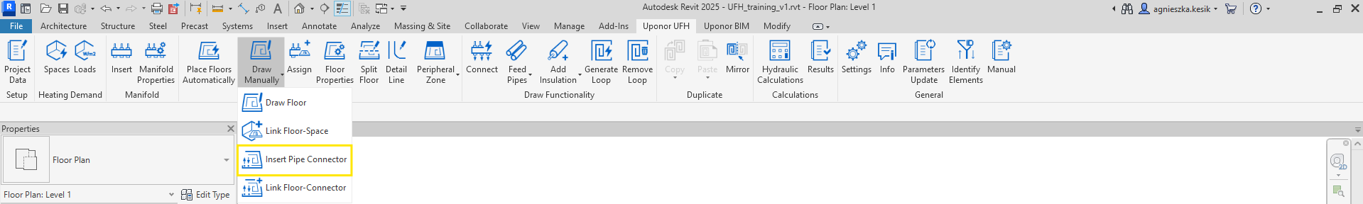
After clicking Insert Pipe Connector function on the ribbon, the Insert Pipe Connector window will appear. There is a possibility to create a floor connector for each floor separately or for all existing floors on the drawing. Using the check all or check none buttons, the user can quickly make a selection.
In most cases there is no need to manually insert connectors – they will be inserted automatically when floor is assigned to the manifold. The user can use this function in exceptional situations e.g. when accidentally deleted the connector.
Visibility of floors on the list
- All objects in current project – if checked, all floors existing in the model will appear on the list.
- Only selected objects – if checked, all selected floors in the model will appear on the list.
- Filter by – helps to filter floors by levels.
- Door source file – indication of the .rvt model which contains information about the door area. Thanks to this, the program will try to insert Pipe Connectors into these transitions to avoid collisions with the wall.
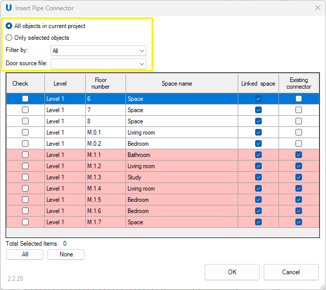
To create Pipe Connector, user should select the checkbox on the left side of the floors table and click OK. It is possible to select multiple floors at once. The Pipe Connector inserted in this way should be automatically linked to the floor. When red rows appear in the list of floors, it means that Pipe Connector have already been create and assigned to the floor. There is also the information if floor is already linked with space.
Link Floor – Connector
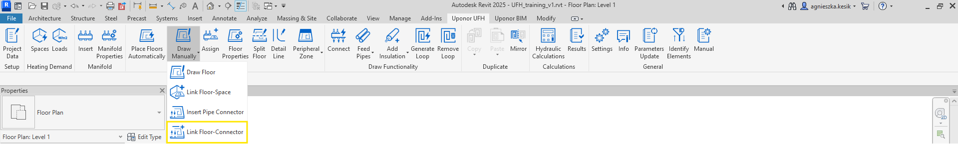
Sometimes Pipe Connector may lose its connection with the floor. Thanks to Link Floor – Connector function, the user can assign a Pipe Connector to specific floor. To assign manually Pipe Connector to corresponding floor, select both elements and use Link Floor – Connector function. Thanks to this, the pipe connector will get important parameters collected in floor. When the user correctly links floor and connector, the following message will appear.

Link Floor-Connector function can be useful when the user accidentally moves a connector from one floor to another and will draw the pipes installation. To make corrections easier, the user should reconnect floors and connectors using above function.